
Yubai New Electric
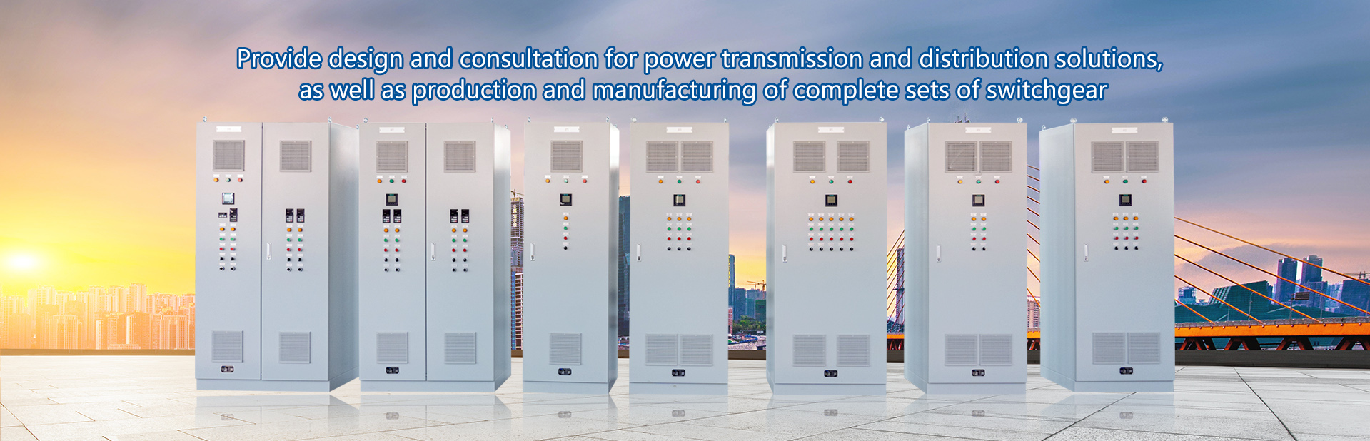
Provide design and consultation for power transmission and distribution solutions
Consultation Hotline:
15050262118

Product Overview
MNS is a modular and multifunctional low-voltage distribution cabinet. Applied to all low voltage systems that require high reliability in metallurgy, petroleum, chemical, industrial and mining enterprises, and infrastructure fields: distribution and motor control systems.
The cabinet structure used by MNS has a high degree of flexibility.
According to your needs or different usage scenarios, various types and specifications of components can be installed in the cabinet;
According to different electrical equipment, multiple types of feeding units can be installed in the same cabinet or cabinet. For example, the feeding circuit and the motor control circuit can be mixed together.
MNS is a full range of low-voltage switchgear that can meet your comprehensive needs. Suitable for all low-voltage systems below 4000A.
MNS can provide a high level of reliability and safety. Humanized design enhances the protection required for personal and equipment safety.
MNS is a fully assembled structure, with its unique profile structure and connection method, as well as compatibility with various components, which can meet the requirements of demanding construction periods and power supply continuity IEC439、GB 7251.1。
Normal usage conditions
1. Application scenarios: power distribution, motor control
2. Execution standards: IEC439、GB7251.1
3. Environmental temperature:- 5℃~40℃
4. When the relative humidity of the environment is 40 ℃, it should not exceed 50%. At lower temperatures, higher relative humidity is allowed, and condensation may occur accidentally (such as 90% at 20 ℃)
5. Installation location: Indoor
6. Altitude: ≤ 2000m
7. If the above conditions cannot be met, the user should raise the issue with the manufacturer when placing an order.
Main technical parameters
1.1 Form of incoming and outgoing lines: cable/bus duct (bridge)
1.2 Cable Entry and Exit: Top/Bottom
1.3 Wiring form: front/back of cabinet
1.4 Protection level: IP30、IP40、IP54
1.5 Function unit isolation form: full isolation or partial isolation
2. Cabinet size
2.1 Height: 2200
2.2 Width: 600, 800, 900, 1000
2.3 Depth *: 600, 800, 1000
2.4 Surface treatment: High voltage electrostatic epoxy powder spraying ≥ 60 μ m
3. Electrical data
3.1 Rated insulation voltage: up to 1000V
3.2 Rated operating voltage: up to 660V
3.3 Rated frequency: 50/60HZ
3.4 Rated impulse withstand voltage: 8kV
3.5 Rated voltage of auxiliary circuit: AC380、220V/DC220V
3.6 Overvoltage level: I
3.7 Pollution level: 3
3.8 Rated current: 4000A
3.9 Rated current of horizontal busbar: 4000A
3.10 Rated current of vertical busbar: 2000, 1000A
4. Horizontal busbar
4.1 Rated short-time withstand current: 50/80kA
4.2 Rated peak withstand current: 105/176KA
5. Vertical busbar
5.1 Rated short-time withstand current: 50kA
5.2 Rated peak withstand current: 105kA
6. Grounding system: TT,IT,TN-S,TN-C-S
7. Maximum incoming and outgoing circuit breaker: 4000A
① The cabinet with glass doors has a minimum depth of 725.
② In order to facilitate the laying of horizontal busbars, for systems arranged in the same manner, the depth of the cabinet should be uniform. If not, a 400 wide busbar adapter cabinet should be added at each connection Cabinets with busbar bridges or busways for incoming and outgoing lines should have a depth of ≥ 800.
*For products with special requirements, please consult the manufacturer
main features
1. In order to facilitate the installation of equipment and on-site construction, a dedicated cable channel is provided in the distribution cabinet, and corresponding cable fixing components are attached
2. The drawer unit is accurately positioned and clearly indicated at each position, and can be locked with up to 3 padlocks at each position
3. The special profile structure and connection method ensure the strength of the cabinet
4. The drawer unit adopts contact wires to directly connect with the 'L' - shaped vertical busbar, which is simple and reliable.
5. The unique 3-section guide rail makes drawer entry and exit more flexible and convenient, and allows for inspection, maintenance, or replacement of internal components and wiring without disconnecting the drawer unit from the cabinet.
Division of areas inside the distribution cabinet
According to the different functions of each part, the distribution cabinet can be divided into four independent compartments.
1. Horizontal busbar room (an independent compartment located behind or on top of the cabinet)
The horizontal busbar is placed behind the cabinet when the front line is outgoing.
1.2 The horizontal busbar is also placed on the top of the cabinet.
2. Vertical busbar compartment (an independent compartment located on the left side behind the cabinet).
The vertical busbar adopts an 'L' - shaped busbar, which is placed in a dedicated fully enclosed functional board. This not only ensures the dynamic stability of the vertical busbar, but also the protection level of its live parts can reach IP20 after the drawer unit is extracted
3. Functional unit room (each independent compartment located on the left side in front of the cabinet) drawer unit or fixed partition unit
4. Cable room
The front outlet is located on the right side in front of the cabinet
When the rear outlet is located on the right side behind the cabinet


Appearance and installation dimensions

